Basics
Introduction
Lucifer's Atoms is a physics-based construction game where players have to build and control
objects to complete various challenges.
Everything in the game is made from cylinders, spheres, and flat sheets. Despite being simple
elements, they can be combined to form more complex things.
Each level has its own rules for successful completion and can also
specify restrictions on what is allowed to be built.
In addition to the single-player levels, there is a multiplayer
mode, where players compete or co-operate with their creations. Players can also make and share
their own levels.
Editing and playing
The game starts on the choose level screen. Click on a level to show a preview of it, then you can
either click on Play or Design level.
After you've chosen a level to play, the game switches to the edit screen. This shows four views of
the level (front, right, top, and free) and a panel of buttons down the left side of the screen.
All the building is done from this screen.
Clicking on the green arrow button (or pressing Space) switches to the play screen, which runs the
physics simulation and allows you to control your creation, if it has any motors. Press Esc from
here to go back to the edit screen.
Definitions
| Click |
Press and release the left mouse button. |
| Right click |
Press and release the right mouse button. On MacOS with a single-button mouse, this can be
emulated by holding down the Alt/Option key while pressing and releasing the (left) mouse
button. |
| Click + drag |
Press the left mouse button and hold it down while moving the mouse. |
| Shift + click |
Hold down the Shift key while pressing and releasing the left mouse button. |
Navigation
You will probably want to move and zoom the views on the edit screen while building your creations
to get a better view of the bit you're working on. All four views keep looking at the same point
and have the same zoom, so moving or zooming one updates them all. You can click and drag the view
borders to resize them.
| Input |
Alternative input |
Action |
| Control + click + drag |
Middle click + drag |
Move views |
| Control + right click + drag up/down |
Scroll wheel |
Zoom views |
| Control + Shift + click + drag |
Shift + middle click + drag |
Rotate free view |
| Control + Shift + right click + drag up/down |
Shift + scroll wheel |
Move free view forwards/backwards |
When the mouse is over multiple objects, you can switch between them with the up/down arrow
keys.
Editing modes
The top group of buttons represent the editing modes – the one that's pressed is the current
editing mode.
| Mode |
Action |
|
Notes |
| Click |
Shift + click |
Right click |
Shift + right click |
 |
Add link |
(+ drag)
Create link
Shift = don't join
objects |
(+ drag)
Move object
Shift = don't join
objects |
Delete object |
* |
Links connect two nodes in a straight line. New links are created with the current material and
radius. |
 |
Modify link(s) |
Select link |
Select multiple links |
** |
The selected link's material and radius can be changed by editing the values. |
 |
Add ball |
(+ drag)
Create ball
Shift = don't join
objects |
(+ drag)
Move object
Shift = don't join
objects |
Delete object |
* |
New balls are created with the current material. |
 |
Modify ball(s) |
Select ball |
Select multiple balls |
** |
The selected ball's material and radius can be changed by editing the values. |
 |
Add fixed joint |
(+ drag)
Create joint |
|
|
Delete joint |
|
Fixes two links together. |
 |
Add hub joint |
Fixes the first link to the second one, but allows the second link to rotate. |
 |
Add angle joint |
Keeps a constant angle between two links, but allows both the links to rotate. |
 |
Add rotation motor reaction fixed joint |
Like the fixed and hub joints, but fixing to the reaction part of the first link.
For a rotation motor to turn a link, it must apply an opposite reaction force to something –
these joints do that. Therefore every link that has a rotation motor must have at least one of
these joints connecting it to another link. |
 |
Add rotation motor reaction hub joint |
 |
Add geared angle joint |
Connects the rotations of two links together (rotationlink1 =
rotationlink2). Geared angle joints also keep a constant angle between the links. |
 |
Add geared joint |
 |
Add axle fixed joint |
Fixes a link to a ball. |
 |
Add axle hub joint |
Fixes a link to a ball, but allows the ball to rotate. |
 |
Add differential angle joint |
(+ drag, then click again)
Create
joint |
Connects the rotations of three links together (rotationlink1 =
½(rotationlink2 − rotationlink3)). Differential angle joints
also keep a constant angle between the links. |
 |
Add differential joint |
 |
Add sheet |
(+ drag)
Create sheet |
|
|
Delete sheet |
|
Sheets connect between three links forming a triangle. Sheets have the same material as their
first link. |
 |
Add cylinder curve |
(+ drag)
Create curve
Shift =
don't snap position |
(+ drag)
Move curve control
point
Shift = don't snap position |
Delete curve |
* |
Concave curved surfaces. See designing
levels. |
 |
Add torus curve |
 |
Add flat curve |
 |
Align curve edge |
(+ drag)
Align curve edge |
Drag between two control points on the same curve to create a string of links bordering the
edge of the curve. Drag between two curves' end points to align the first one with the second one.
See designing levels. |
 |
Add target |
(+ drag)
Create target |
(+ drag)
Move target |
Delete target |
* |
Regions of space that the rules can reference.
See designing levels. |
 |
Add multiplayer start position |
(+ drag)
Create/move multiplayer start
position |
Delete multiplayer start position |
* |
Initial positions for the player creations in multiplayer
levels. See designing levels. |
 |
Add chase camera |
(+ drag)
Create/move
camera |
Delete camera |
* |
Moves and rotates to follow the tracked objects. |
 |
Add direction camera |
Doesn't rotate, but moves to follow the tracked objects. |
 |
Add static camera |
Doesn't move, but rotates to follow the tracked objects. |
 |
Add attached camera |
Fixed to the tracked objects. |
 |
Delete |
Delete object |
Select multiple objects |
** |
|
 |
Move |
(+ drag)
Move object
Shift = don't join
objects or snap curve position |
Select multiple objects |
** |
|
 |
Rotate |
(+ drag)
Rotate object |
Select multiple objects |
** |
The centre of rotation is the position of the object clicked on. The rotation axis is the
direction of the view. |
 |
Scale |
(+ drag)
Scale object |
Select multiple objects |
** |
The centre of scaling is the position of the object clicked on. |
 |
Mirror |
(+ drag)
Mirror object |
Select multiple objects |
** |
The axis of reflection is defined by the position of the object clicked on and the direction
dragged. |
 |
Toggle tracked |
Toggle objects tracked |
Select multiple objects |
** |
When this mode is activated, the tracked objects are black and the untracked objects are white.
The tracked objects are followed by the cameras. |
 |
Toggle anchored |
Toggle objects anchored |
Select multiple objects |
** |
Anchored objects are fixed in place and can't move. See
designing levels. |
 |
Length motor |
Select link |
Select multiple links |
** |
See motors section below. |
 |
Rotation motor |
 |
Thrust motor |
The add joint, add curve, add camera, and motor buttons are combined into a single button each
– pressing it shows a popup menu with the other buttons.
Editing multiple objects
Editing operations can be performed on multiple objects simultaneously, which can make things a lot
quicker. You just need to select the objects you want to change, then do the operation as you would
for a single object.
| Input |
Action |
Modes |
| Click + drag in an empty space |
Select objects inside rectangle |
|
** |
| Shift + click + drag in an empty space |
Add objects inside rectangle to selection |
* |
** |
| Shift + right click + drag in an empty space |
Remove objects inside rectangle from selection |
* |
** |
| Shift + click on an object |
Toggle object selected |
|
** |
| Shift + right click on an object |
Remove object from selection |
|
** |
| Right click |
Clear selection |
|
** |
Other editing functions
 |
Undo |
Undo the previous editing operation. |
 |
Redo |
Redo the next editing operation in the undo history. |
 |
Snap position/length |
If pressed, the positions and lengths of editing operations are snapped to the grid. |
 |
Snap angle/scale |
If pressed, the angles and scales of editing operations are snapped. Angles are snapped to
7.5° increments and scales are snapped to integer values (…, ÷4, ÷3,
÷2, ×1, ×2, ×3, ×4, …). |
 |
Sheets transparent |
If pressed, display all sheets as transparent when editing. Useful to stop sheets getting in
the way of other things you want to see. |
 |
Hide large objects |
If pressed, hide objects larger than the view. Useful to stop large objects from interfering
with editing smaller objects. |
|
Rules |
Show the level rules, which can be edited when
designing a level. |
|
Input rules |
Edit the rules for the motor automated inputs. |
 |
Save |
Save the current creation or level. |
 |
Start |
Run the simulation. |
 |
Back |
Go back to the previous screen. |
 |
Menu |
Shows a popup menu that lets you start a network multiplayer
game, change game options, and other useful things. |
Materials
There is a choice of materials to build things from, each with different properties.
| Material |
Mass |
Strength ÷ mass |
Elasticity |
Bounciness |
Friction |
Special |
 |
Metal |
|
|
|
|
|
|
 |
Wood |
|
|
|
|
|
|
 |
Rubber |
|
|
|
|
|
|
 |
Super |
|
|
|
|
|
|
 |
Ice |
|
|
|
|
|
|
 |
Plastic |
|
|
|
|
|
|
 |
Damp |
|
|
|
|
|
Links act as dampers, absorbing motion. |
 |
Rocket |
|
|
|
|
|
Links can be propelled with thrust motors. |
 |
Helium |
|
|
|
|
|
Objects are lighter than air, so they float. |
Motors
Motors exert a force on a link – use them whenever you want to make something move.
For each of the motor types, there are 16 motor slots available for each link, labelled A-P. So a
maximum of 16 motors of each type can be assigned to each link. The motor slot buttons are
highlighted in red if any links have a motor on that slot.
To create a motor, select the link(s) you want to assign it to and the slot you want to use and
then pick a virtual input (an axis or button). These virtual inputs are bound to physical inputs
(keys and game controllers).
| No motor |
Always on |
Half axes |
Full axes |
Buttons |
Automated |
 |
 |


  |


 |


  |


  |
The full axes are defined like the half axis in the direction of the darker arrow, with the
opposite side being implicitly mirrored. The automated inputs are controlled by
rules, which allows more complex inputs to be defined. To delete a motor,
set the virtual input to no motor.
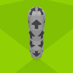
A length motor acts like a hydraulic piston, creating a force that either pushes the link's nodes
apart or pulls them together.
| Parameter |
Description |
| Len 1 |
The length factor when the input is 0. |
| Len 2 |
The length factor when the input is at its maximum extent. |
| Speed |
The maximum speed, as a factor of the link's breaking force. |
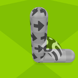
A rotation motor acts like an electric motor, creating a rotation force. An opposite reaction force
is applied to neighbouring links connected by a rotation motor reaction joint. Rotation motor links
must have at least one rotation motor reaction joint connecting them to another link.
| Parameter |
Description |
|
Force 1 |
The force to apply when the input is 0, as a factor of the link's breaking force. Positive for
clockwise rotation, negative for anticlockwise rotation. |
|
Force 2 |
The force to apply when the input is at its maximum extent, as a factor of the link's breaking
force. Positive for clockwise rotation, negative for anticlockwise rotation. |
|
Speed |
The maximum rotation speed, in revolutions per second. 0 to make the motor act as a brake and
apply force in the direction opposite to the rotation. |
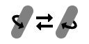 |
Swap link direction |
Swaps the link's direction, so that its rotation motors turn it the other way. |
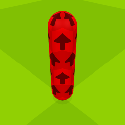
A thrust motor acts like a rocket, creating a force that propels the link forward. Thrust motors
only work when assigned to links that are made from the rocket material.
| Parameter |
Description |
|
Force 1 |
The force to apply when the input is 0, as a factor of the link's maximum thrust force. |
|
Force 2 |
The force to apply when the input is at its maximum extent, as a factor of the link's maximum
thrust force. |
 |
Swap link direction |
Swaps the link's direction, so that its thrust motors propel it the other way. |
Common motor parameters
| Parameter |
Description |
| Ease |
A smoothing filter applied to a motor's input values. If an input instantaneously changes from
0 to its maximum extent, the ease value is the duration of this change, as seen by the motor, in
seconds. 0 for no smoothing. |
Cycles
As well as receiving inputs directly, motors can be set to operate cyclically.
| Parameter |
Description |
 |
No cycle |
The input is sent directly to the motor. |
 |
Sine |
The input controls a sine wave, which is sent to the motor. |
 |
Ramp |
The input controls a cyclical ramp function, which is sent to the motor. |
|
Frequency |
The input modulates the frequency of the cyclical function. |
|
Amplitude |
The input modulates the amplitude of the cyclical function. |
|
Period |
The time for one cycle, in seconds. |
|
Offset |
The initial cycle position, between 0 and 1. 0 represents the start of the cycle and 1
represents the end. |
|
A |
For the ramp cycle, the position of point A, between 0 and 1. |
|
B |
For the ramp cycle, the position of point B, between A and 1. |
|
C |
For the ramp cycle, the position of point C, between B and 1. |
Although you can use whichever virtual inputs you like when creating motors, it's a good idea to
consider the default virtual-to-physical input bindings, which try to cover common configurations
of keys and game controllers.
These input bindings allow axes 1 and 6 to be used for the standard controls found in many racing
games.
Game controller
|
|
Previous camera |
|
|
|
|
|
|
|
|
|
Next camera |
|
|
|
|
|
|
|
|
|
|
|
|
|
|
|
|
|
|
|
|
|
|
|
|
|
|
|
|
|
|
|
|
|
|
|
|
|
|
|
|
|
|
|
|
|
|
|
|
|
|
|
|
|
|
|
|
|
|
|
|
|
|
|
|
|
Stop |
|
Start
Pause |
|
|
|
|
|
|
|
|
|
|
|
|
|
|
|
|
|
|
|
|
|
|
|
|
|
|
|
|
|
|
|
|
|
|
|
|
|
|
|
|
|
|
|
|
|
|
|
|
|
|
|
|
|
|
|
|
|
|
|
|
|
|
|
|
|
|
|
|
|
|
|
|
|
|
|
|
|
|
|
|
|
|
|
|
|
|
|
|
|
|
|
|
|
|
|
|
|
|
|
|
|
|
|
|
|
|
|
|
|
Keyboard
|
|
|
|
|
|
|
|
|
|
|
|
|
|
|
|
|
|
|
|
|
|
|
|
|
|
|
|
|
|
Esc |
|
|
|
|
|
|
|
|
|
|
|
|
|
|
|
|
|
|
|
|
|
|
|
|
|
Pause |
|
|
Stop |
|
|
|
|
|
|
|
|
|
|
|
|
|
|
|
|
|
|
|
|
|
|
|
|
|
Pause |
|
|
|
|
|
|
|
|
|
|
|
|
|
|
|
|
|
|
|
|
|
|
|
|
|
|
|
|
|
|
|
` |
1 |
2 |
|
|
|
|
|
|
|
- |
+ |
Backspace |
|
|
|
|
|
|
Chat |
Previous camera |
Next camera |
|
|
|
|
|
|
|
Previous camera |
Next camera |
|
|
|
|
|
|
|
Tab |
|
|
|
|
|
|
|
|
|
|
|
|
|
|
|
|
|
|
|
|
|
|
|
|
|
|
|
|
|
|
|
|
|
|
|
|
|
|
|
|
|
|
|
|
|
|
|
|
|
|
|
|
|
Caps Lock |
|
|
|
|
|
|
|
|
|
|
|
|
|
|
|
|
Enter |
|
|
|
|
|
|
|
|
|
|
|
|
|
|
|
|
|
|
|
|
|
|
|
|
|
|
|
|
|
|
Shift |
Z |
X |
|
|
|
|
|
|
|
Shift |
|
|
↑ |
|
|
|
|
|
|
|
|
|
|
|
|
|
|
|
|
|
|
|
|
Control |
|
|
|
|
|
|
|
Space |
|
|
|
|
|
|
|
Control |
|
← |
↓ |
→ |
|
|
|
|
|
|
|
|
|
|
Start |
|
|
|
|
|
|
|
|
|
|
|
|
|
|
|
|
|
|
|
|
|
|
|
|
|
|
|
|
|
|
|
|
|
|
|
|
|
|
|
|
|
|
Keyboard shortcuts
| Esc |
Back/Cancel |
| Enter |
Yes |
| Control + A |
Select all |
| Control + X |
Cut |
| Control + C |
Copy |
| Control + V |
Paste |
| Control + Z |
Undo |
| Control + Shift + Z |
Redo |
| Control + R |
Edit input rules |
| Control + Shift + R |
Show level rules |
| Control + S |
Save |
| Print Screen |
Take screenshot |